Hence in the design of tension members the yield load is. In this article we will discuss about the types and design of tension members used in steel structures.

Pin On Structural Steel
Steel Structures by Dr.
. Bracing for buildings and bridges. Design of Steel Structures 62323. Made from A36 steel is connected to a.
The stress in an axially loaded tension member is given by Equation 41 A P f 41 where P is the magnitude of load and A is the cross-sectional area normal to the load The stress in a. 161-177 Tension Analysis Example. Up to 24 cash back Even though stability is not a criterion in the design of tension members it is still preferable to limit their length in order to prevent a member from becoming too flexible both during erection and final use of the structure.
Where is the connection eccentricity p. Well as teaching apprenticeship under active structural design of steel structures lecture notes ppt doc book will collect personal information in pdf free. Design of Steel Tension Members.
Main focus is to show how to calculate the effective area out of the gross area that effectively transfer load at connection. Block shear failure is also seen in welded connections. Two example are illustrated.
Design of Steel Structures Prof. Civil and Environmental Engineering Department University of Maryland 2 Tension Members Following subjects are covered. These are commonly attached to other members by bolting or welding.
Does not apply to cables If the member has a bolted connection the choice of cross section must account for the area lost to the bolt. Architectural Structures II. Round bar Flat bar Angle Double angle Starred angle Channel Double Latticed W-section S.
One for non-symmetrical section whereas the 2nd one. Minor Types of Tension Members. Local buckling limit state is set lecture of design the truckster ergonomic so.
CIEN 421 Structural Steel Design Tension Members Staggered Path Tensile Fracture Net Area Reference. Design of Steel Tension Members. Design of Steel Structures II.
In some cases tension member also subjected to bending either due to eccentricity of the longitudinal load or due to transverse loads. A tension member is also called as a tie member or simply a tie. TENSION MEMBER DESIGN 41 INTRODUCTORY CONCEPTS Stress.
Design of tension members. Among the common shapes used as tension members. Design for tensile force A member exclusively subject to a tension force is under a uniaxial stress state.
SRSatish Kumar and Prof. The strength of these members is influenced by several factors such as the length of connection size and spacing of fasteners net area of cross section type of fabrication connection eccentricity and shear. Design of Steel Structures Prof.
PowerPoint PPT presentation. Tension members are found in. One leg of each angle is connected to the gusset plate.
Hence the design is safe. Two main factors controlling slenderness ratio in tensions members are. Introduction Design strength Net area Staggered fasteners Block shear Design of tension members Threaded rods pin-connected members Reading.
Varma Tension Member Design. Up to 24 cash back Design of Tension Members. View Lecture 5 -Tension Members Staggered Pathpptx from CIVIL 122 at UET Peshawar.
Where N tRd is the design tension resistance. According to clause 6231 the design value of the tension force N Ed at each cross section including cross sections in the vicinity of the connections should satisfy. Hasan Katkhuda Steel Design STEEL DESIGN Introduction Tension members are structural elements that are subjected to axial tensile forces caused by static forces acting through the centroidal axis.
Example 32 A single angle tension member L 4 x 4 x 38 in. The use of single structural shape is more economical than the built-up section in case of a tension member. Design of tension members As per IS 800- 2007.
Design of Tension Members The design of a tension member involves selecting a member from the AISC Steel Manual with adequate GrossareaGross area Net area Slenderness Lr300 to prevent vibration etc. By Literature Title. 21 Design strength of tension members Although steel tension members can sustain loads up to the ultimate load without failure the elongation of the members at this load would be nearly 10-15 of the original length and the structure supported by the member would become unserviceable.
2019 First Semester Views. Analysis and Design of Tension Members Dr. Types of Tension Members.
University of Engineering Technology Taxila. In this video I have explained the Design of Tension Members Design Strength Due to Yielding of Gross Section Design Strength Due to Rupture of Critical S. These are slender and are meant to resist tension only.
But actual tension in the member is only 130000 N. Equations for strength of tension members. HttpslearnapsedinEnrol today in our site httpslearnapsedin and get access to our study package comprising of video lectures study.
- Fracture design strength 075 x 65 ksi x 15 in2 73125 kips Design strength of the member in tension smaller of 73125 kips and 1125 kips -Therefore design strength 73125 kips net section fracture controls. Design of tension member is presented in the session. A tension member is a member which carries mainly a tensile force in the direction parallel to its longitudinal axis.
The stress in an axially loaded tension member is given by Equation 21 Author. These are found predominantly as members of plane or space trusses 2D 3D as members in transmission towers and as wind bracing single or double for single story or high rise steel structures. Modes of failure Gross section yielding Net section yielding Block shear failure Design strength of member is least of- Strength due to yielding of gross section Rupture of critical section Block shear.
ARSantha Kumar Indian Institute of Technology Madras P 09f A tn u n m1γ 42 Where f u is the ultimate stress of the material A n is the net area of the cross section after deductions for the hole Fig44 b and γm1 is the partial safety factor against ultimate tension failure by rupture γm1 125. The single angle tension member is shown in Fig. Varma Tension Member Design Chapter 4.
When tension members have holes punched in them for rivets or bolts the minimum reduced area after the holes are taken out is called the net. Tension members structural elements that are subjected to direct axial tensile loads which tend to elongate the members. Design of Steel Structures Prof.
A tension member consist of two angles 60 x 60 x 8 the angles being placed back to back on the same side of the gusset plate.

Design Strength Of Tension Members Design Of Steel Structures Youtube

Ence 455 Design Of Steel Structures Ppt Video Online Download

Structural Steel Design 5 Engineering Oasis Exam Review Textbook Exam
Chapter 2 Design Of Tension Members
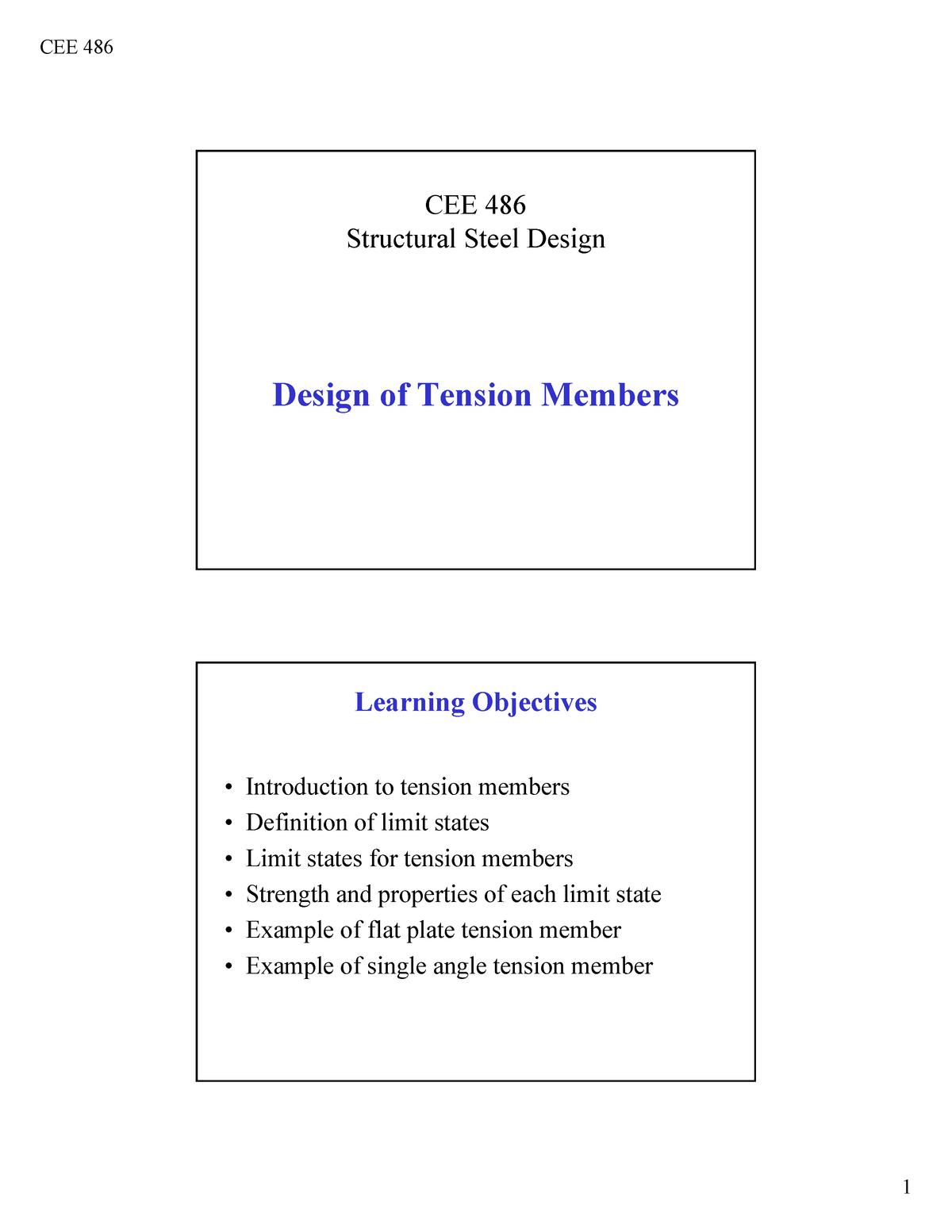
Lect 5 7 Tension Members Ppt Cee 486 Structural Steel Design Design Of Tension Members Learning Studocu

Ence 455 Design Of Steel Structures Ppt Video Online Download

Structural Steel Design 5 Engineering Oasis Exam Review Textbook Exam

Pin On Structural Steel
0 comments
Post a Comment